Cameras Automation (3)
RTSP URL
Regardless of the software used, it is necessary to specify the RSTP video address to capture the video stream from a camera.
The RTSP URL must have at least the IP address of the camera and a format. For example: rtsp://192.168.14.2/avc
You can also include more options like this: rtsp://192.168.14.2/avc/ch1&?cbr=0&quant=80&frate=30&gop=1
Video formats
Each FLIR camera model has different video formats: consult the camera's user manual to confirm the video formats available on your camera.

URL parameters
The available parameters are listed below. These parameters are not valid for the MJLS format, nor for A3xx camera models.
- {ch0|ch1} 0=IR(default), 1=visible
- frate {framerate in Hz}
- overlay {on|off}
- cbr {constant bit rate in bits per second, 0=variable bit rate}
- quant {quality level -1 to 100 where 100 is the best quality, valid only if cbr=0}
- gop {group of images, gop is the sum of a keyframe + intended frames, i.e. the number of P frames following a frame I}
Instructions for using VLC Media Player
The following examples were made with a FLIR AX8 and VLC Player version 2.2.1. You can download the software free of charge at https://www.videolan.org/.
Step 1: Set the IP address of the camera
Before you can connect to the camera, you must configure its IP address to be on the same subnet as your computer.
Most of the cameras in this answer can be configured using FLIR IP Config.
See this link if you are not familiar with IP networks: IP Addressing Basics.
Step 2: Video transmission configuration
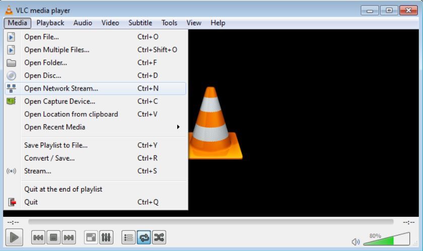
Open VLC Media Player, click on the "Media" tab and then on "Open Network Stream...".

Step 3: Connect to the camera stream
With IP address 169.254.79.239. The AX8 supports three different video formats: AVC (h.264), MPEG4 and MJPEG. This example shows how to connect to the AVC format. Type the address of the video stream (rtsp://169.254.79.239/avc) and click Play.

The video will be shown.

Step 4: Record a live video
The recording commands appear on the Playback tab. To record the video, click Record. To stop recording, click Stop.

Los vídeos grabados se guardan automáticamente en C:\Usuario\<su_usuario>\Videos. Puede acceder al vídeo yendo a la dirección de la carpeta o abriendo la carpeta Bibliotecas y luego abriendo Vídeos.
There are also other ways to access the record button. Some examples are:
Right-clicking on the video.

Step 5: Save the recording to a file
This is easily achieved with the VLC media player which can be downloaded from here.
Once VLC is installed and the camera is connected to the computer. Click on Media and click on Open Network Stream...
Choose the Network tab and enter RTSP:IP address of the camera. Then click Convert in the scroll bar.

Browse to the desired folder and create a file. This is the file that will contain your RTSP video.


Now just let the camera run and once you no longer want to record a video, press stop and the video will be saved to your hard drive.
If you have any doubts or questions, please contact us.
IR monitor and IP configuration
FLIR IP Config is used to determine and set the IP address of FLIR network cameras, typically FLIR A3xx series, FLIR AX8 or FLIR A400/A700 smart cameras.
Older versions of IP Config are available for those who have problems running version 3.0 on their system. See the software downloads page for details.
Click to download the latest version of FLIR IP Config
Click to download the latest version of FLIR IR Monitor
FLIR IR Monitor can be used to install and configure the A310 and A300 cameras. This tool should be used for configuration only and is not intended for continuous video streaming.
Drivers
When using the A310 on Windows machines, it is necessary to download the following drivers:
Click to download FLIR Streaming Drivers 32-bit
Click to download FLIR Streaming Drivers 64-bit
If you have any doubts or questions, please contact us.
Like any framework, Spinnaker has a learning curve. This answer should help you with the basics of using the SDK to control the camera and will point you to more detailed resources on specific topics.
A great first resource is our set of Spinnaker examples that are installed along with the SDK. Our examples can be found at:
- Windows: C:\Program Files "FLIR Systems" (or C:\Program Files "Point Grey Research" for Spinnaker 1.)
- Linux: /opt/spinnaker/src (or /usr/src/spinnaker/src for versions 2.1 and earlier)
- macOS: /Applications/Spinnaker/src
- Python: In the Examples folder of the PySpin download.
The Acquisition example is the best place to start. This answer will reference the Acquisition example throughout; it will focus on the C++ version, but the same steps are followed in other languages with minor syntax differences.
How can I access my camera via the API?
This is quite simple and is a common pattern in any Spinnaker code. First you get an instance of the Spinnaker System:
SystemPtr system = System::GetInstance();
Then use this system object to obtain a list of all cameras connected to the system:
CameraList camList = system->GetCameras();
Finally, get the camera from the list. The easiest way to do this is with the GetByIndex method:
CameraPtr pCam = camList.GetByIndex(i);
How do I start transmitting the camera and taking images?
The code to achieve this is also simple, but there are some important concepts to keep in mind. Start the camera transmission with
pCam->BeginAcquisition();
This causes the camera to start acquiring images. It is important to note that at this point, the camera is running asynchronously to the code. In simple terms, after the camera begins acquisition, it will continue to capture images, even while the program is doing nothing. Once the camera captures an image, it is automatically transferred to the PC and stored in the PC's RAM. The space allocated to store that image in memory is called a buffer. A user can only interact with an image once it has been retrieved from the buffer using this method:
ImagePtr pResultImage = pCam->GetNextImage(1000);
The asynchronous nature of the system means that GetNextImage must be called approximately as often as the camera captures an image to avoid losing frames. If GetNextImage is not called often enough, the image buffer may fill up and frames may be lost.
How can I change the camera settings?
This is done through the camera's nodemap which can be accessed with
INodeMap& nodeMap = pCam->GetNodeMap();
Using Spinview to accelerate debugging and development
Spinview is a GUI software that is installed together with Spinnaker. Although it is designed as a demonstration software to show the camera features, this GUI can be very useful during application development. With Spinview it is very easy to quickly read and write to the camera nodemap. At the beginning of development, we recommend using Spinview to configure the camera as desired. This will help to visualize the required node operations, as well as to verify that the camera is able to operate as desired. A quick guide to Spinview is available
Restoration of machine vision cameras
Occasionally, cameras may fall into a bad state and need to be recovered. The easiest way to recover from this is to load the factory default settings on the camera by loading the default user set.
If you have any doubts or questions, please contact us.
OEM cameras (1)
FLIR Boson App is compatible with the operation of Boson cores. The GUI is a PC-based program that allows remote command and control of many commonly used camera functions and features via a USB or UART interface to the camera. Drivers are included. The Boson GUI is available for free download at https://www.flir.com/support-center/oem/camera-controller-gui-for-boson/. A camera is not required to run the GUI and view its capabilities.
The Boson Software Development Kit (SDK) is available free of charge. It provides a command and control interface, but does not give access to video transmission. The USB video transmission can be controlled via a standard UVC interface. The boson application, webcamviewer, or the native camera application for Windows will stream video.
The FLIR camera control graphical user interface (GUI) supports the operation of legacy Tau 2, Quark 2 and Photon cameras. The GUI is a PC program that allows remote command and control of many commonly used camera functions and features via an RS-232 serial interface to the camera. Drivers are included that allow control of the Tau2 camera via USB protocol. The camera control GUI is available as a free download at https://www.flir.com/support-center/oem/vue-camera-controller-gui/. A camera is not required to run the GUI and view its capabilities. Customers wishing to develop their own custom interface for legacy Tau2, Quark2 and Photon cameras can purchase a software development kit (SDK). Ordering information for the SDK and other camera accessories can be found at https://www.apliter.com/producto/sdk-para-para-flir-tau/.
If you have any doubts or questions, please contact us.
Portable Cameras (2)
Depending on the configuration of your IR camera, you can connect the camera to a wireless local area network via Wi-Fi (Connect to Network), or let the camera provide a Wi-Fi access point (Share) to another device. You can connect the camera in two different ways.
The most common use:
Set the camera as a Wi-Fi access point (Sharing). This method is used with an iOS device (iPhone or iPad).
Less common use:
Connect the camera to a WLAN (Connect to the network). This method is used with an Android device.
How to connect the IR camera to an iOS device (iPhone, iPad):
1. Press the center of the navigation panel to display the menu system. 2.
2. Select "Configuration" and click in the center of the navigation panel. The Setup menu appears.
3. Use the navigation button to select Connections > Wi-Fi.
4. Select Share and click in the center of the navigation pane.
(Optional step.) To display and change the parameters, select Share and click in the center of the navigation panel.
- To change the SSID, select Network Name (SSID) and click in the center of the navigation panel.
- To change the WPA2 password, select Password and click in the center of the navigation panel.
How to connect the IR camera to an Android device:
- Press the center of the navigation panel to display the menu system.
2. Select "Configuration" and click in the center of the navigation panel. The Setup menu appears.
3. Use the navigation button to select Connections > Wi-Fi.
4. Select Connect to the network and click in the center of the navigation panel.
5. To display a list of available networks, select Available networks by clicking in the center of the navigation panel.
6. Select one of the available networks and click in the center of the navigation panel.
Once these steps are completed, you can use FLIR Tools Mobile on your devices to initiate the connection.
FLIR Tools Mobile can be downloaded from the App Store for an iPhone or iPad and from the Google Play Store for Android devices.
If you have any doubts or questions, please contact us.
In order for FLIR ONE for Android to work with an Android phone, you must consider the following:
- Android version must be 5.0 or higher. A list of compatible devices can be found here.
- Your phone must support USB OTG (On The Go). OTG is a protocol in which USB allows tablets or smartphones to act as hosts so that other USB devices such as USB sticks, digital cameras, mice or keyboards can be recognized. To check that your phone supports OTG, please contact your phone manufacturer.
Depending on your phone and the version of FLIR ONE you have, your connections may be different and an adapter may be required. Check the following.
Phones with Micro-USB connector
If your phone has a Micro-USB port and your FLIR ONE has a different connector, then you need an adapter for the camera to fit the phone. You can use any of the commercially available brands, but the adapter must be OTG compatible.
Phones with USB Type-C connector

If your phone has a USB Type-C socket and your FLIR ONE has a Micro-USB connector, you need an adapter. You can use any of the commercially available brands, but the adapter must be OTG compatible.
Disclaimer: Non-manufacturer branded adapters have not been tested directly by FLIR. If you have questions, please make an inquiry to contact one of our product specialists.
If you have any doubts or questions, please contact us.
Thermal Imaging Cameras OGI - Optical Gas Imaging ( 1)
QOGI stands for Quantitative Optical Gas Imaging and is the latest technology related to Leaking Detection And Repair (LDAR). QOGI uses FLIR's existing OGI cameras (the GF320, GFx320 and GF620) to quantify hydrocarbon gas leaks.
FLIR QOGI Solutions
The FLIR QL320 is the latest platform to run the advanced QOGI method to easily quantify gas leakage in units of mass leak rate, volumetric leak rate or by concentration length.
QOGI Triangle
To obtain a quantifiable image of a gas with an infrared camera requires three things. We describe this as the "QOGI triangle", similar to the "fire triangle", where fuel, oxygen and ignition are needed. These requirements are listed below:
- α(λ): Gas has an IR absorption peak that overlaps with spectral filter of the OGI chamber.
- ΔT: There is a sufficient temperature differential between the gas plume and the bottom.
- CL: There is sufficient gas concentration in the plume.

If you have any doubts or questions, please contact us.
Drones (1)
WHAT IS THE DIFFERENCE BETWEEN 30 HZ AND 9 HZ?
Las cámaras de vídeo emiten una serie de imágenes «fijas» a un ritmo regular, un ritmo dado en hercios (Hz) o en fotogramas por segundo (fps). Las cámaras UAS de FLIR con vídeo de 25 a 60 fps emiten ese número de fotogramas únicos por segundo. Para facilitar el transporte de las cámaras a través de las fronteras, existe una clase de cámaras «<9 Hz». Estas cámaras envían fotogramas de vídeo a una velocidad normal, pero estos fotogramas se duplican durante intervalos cortos. El resultado es una frecuencia de imagen efectiva inferior a 9 fps. Póngase en contacto con un especialista en exportación antes de transportar cualquier cámara térmica de un país a otro.
CAN I EXPORT OR TRAVEL INTERNATIONALLY WITH MY THERMAL CAMERA?
There are international regulations on the transport and movement of all thermal cameras. Export laws allow thermal cameras with frame rates below 9 frames per second (fps) to move more freely across borders than 60 or 30 fps cameras. Contact an export specialist for more details.
WHAT IS THE DIFFERENCE BETWEEN 160 × 120, 336 × 256 AND 640 × 512 RESOLUTION CAMERAS?
Each FLIR UAS thermal camera has an imaging device known as a focal plane that converts the target image into pixels. The sizes 160 × 120, 336 × 256 and 640 × 512 are examples of the resolution options available for these cameras. The first value represents the number of horizontal pixels and the second number represents the number of vertical pixels. At first glance, many people assume that the 640 has twice the resolution of the 336, but in reality the total number of pixels is 3.8 times greater. The 336 × 256 offers 86,016 total pixels and the 640 × 512 offers 327,680 pixels.
WHAT IS THE FIELD OF VIEW?
The field of view, also referred to as FOV, is the degree of visibility that the camera lens provides to the sensor. For example, each pixel in the 640 × 512, 13 mm configuration (45 × 37 degree FOV) will represent an angle of 0.07 degrees per pixel, which means that at 30.5m, each pixel is imaging 4cm. From a less technical point of view, FOV equals the observable area that can be imaged with the lens. The graphs below show how various FOVs on 640 and 256 cameras correspond to the observable area when looking down. The calculation is linear, so an elevation of 60 meters would double the value, while an elevation of 50 feet would be half the value.

WHAT IS THE BEST LENS FOR MY CASE?
There are two main considerations in determining the best lens and resolution for a given application. First, the field of view (FOV) is the approximate angle of the observable image. Figure 2 shows the observable area per lens model at 30.5 meters (100ft) AGL assuming you are looking straight down.

The second factor is the angle that each pixel represents, known as iFOV. Knowing the angle of each pixel helps to calculate the number of pixels that would appear for various targets at different distances. For temperature measurement, an object should appear at least in a 5 × 5 pixel grid, but 10 × 10 or more will give even better results. The target should be chosen so that the FOV is wide enough to find what you are looking for, and that the iFOV allows enough "pixels on target" at the desired flight altitude.
Figure 2 shows the spot size at 30.5 meter AGL when looking down. Worldwide, the 640 × 512, 13 mm option is the number 1 selling model and performs most tasks very well.
*AGL(Above Ground Level) = Above ground level
WHAT SHOULD I BUY?
Camera systems are usually available as a package with a compatible drone. This is the easiest way to ensure compatibility. There are gimbal packages available that target specific cameras on specific drones or drone families. They may be available through the vehicle manufacturer or third parties. The documentation for each stabilizer will identify the cameras and vehicles with which it is compatible.
To integrate a general-purpose sUAS camera into your existing drone, a number of factors need to be considered.
Weight and center of gravity (CG): The drone must be able to lift the camera and still maintain a useful flight time. Some measures need to be taken to support the camera on the vehicle and maintain balance. FLIR UAS cameras typically have a ¼-20 threaded hole on the top, bottom, or both sides of the camera. These holes are the same size and thread pattern found on consumer cameras, so they can be used on tripods.
Power supply: Most FLIR cameras are designed to draw power directly from the vehicle battery, while others draw regulated 5 volts from a battery elimination circuit (BEC). The voltage and current requirements for each camera can be found in the camera's data sheet or user's guide.
Video: The camera may have HDMI or composite video outputs. If real-time video is required for your mission, a compatible video downlink system must be provided.
Camera and stabilizer control: Various features of the camera and any associated gimbal will need to be controlled. Often, this is done using PWM servo signals. These are three-pin outputs from the flight controller or remote control receiver that are used to control motor controllers, servo actuators and other vehicle components.
GPS: Some cameras have built-in GPS receivers to geotag image files. These receivers may need to be connected to external antennas, which are usually placed on top of the vehicle to get the best possible satellite reception. Some cameras do not have internal GPS receivers, and if the image files are to be geotagged, the GPS information from the vehicle will have to be sent to the camera. Typically, this will be done using MAVLink. The engineering data sheet or user's guide will list the available interfaces and their capabilities.
CAN I DETECT METHANE GAS LEAKS WITH MY THERMAL CAMERA?
IR gas detection cameras work by detecting the absorption of light or thermal energy by gases. This absorption is usually weak and in a narrow spectrum, so specialized optical filters and high quality sensors are required. General purpose thermal cameras do not detect these gases reliably. Gas detection chambers are specially designed with narrow optical filters and usually contain a cryogenic cooler, which consumes additional power and adds weight. Take a look at gas detection chambers here: OGI chambers.
HOW HIGH CAN I FLY WITH MY THERMAL CAMERA?
The maximum allowable altitude can be found in the environmental specifications of the product data sheet.
Although typically 11,500 meters MSL for most products, UAS vehicles must be operated in accordance with applicable laws. In addition, camera resolution imposes practical limitations on useful altitudes. At an altitude of120 meters, one pixel on a VUE Pro R camera with a 13 mm lens would represent an area more than 6 centimeters wide. For most thermal imaging applications, the lens would have to be much closer to provide enough pixels on the lens to make the image useful, or a camera with a different lens must be used. For example, at the same altitude of 400 feet (120 meters) and with a 25 mm lens, one pixel would represent an area ~3.4 inches (8.6 cm) in diameter. To measure temperature, an object must appear as at least a 5 × 5 pixel object in the image. Even better results are obtained with 10 × 10.
* MSL (Mean Sea Level) = Above sea level
HOW FAR CAN I SEE DEPENDING ON THE OBJECTIVE CHOSEN?
There is no practical limit to how far a thermal camera can see through a clear line of sight, but it is important to understand what you are looking at. The moon is usually visible when it is not obscured by clouds (water vapor absorbs IR energy). Viewed from Earth, the moon subtends an angle of about 0.5 degrees, so in a 25-degree FOV, 640-resolution camera, the moon would appear as a circle about 12 pixels wide.
The normal limit for the target distance of an IR camera is the size in pixels that the object will appear in the image and the number of pixels required to identify or extract the necessary information about the target. For example, as shown in the image, do you want to detect, recognize or identify the person in the image? The number of pixels you place on an item allows you to make the determination. To measure temperature, an object must appear as at least a 5 × 5 pixel object in the image. With 10 × 10 you get even better results.

CAN I CREATE 3D ORTHOMOSAICS WITH MY THERMAL DATA SETS?
FLIR does not currently offer tools to create thermal orthomosaics. For mapping operations, third-party thermal orthomosaic services with expertise in thermal camera image processing are available. Currently, the ability to retain radiometric temperature data at the pixel level is lost in the orthomosaic creation process.
WHICH SOFTWARE IS BEST FOR MY THERMAL DATA SET OR MY OPERATION?
Different cameras offer different file types and features. In addition, different applications have different requirements. Higher resolution thermal cameras (320 × 256 or more) can achieve a better level of detail by saving the images in the -R.JPEG format and processing them with the free FLIR Thermal Studio Starter application. This combination allows post-flight adjustment of radiometric parameters and provides a simple framework for generating reports. CSV files of the pixel values can also be created for further processing. FLIR Thermal Studio offers batch processing for jobs requiring a large number of files.
WHICH STABILIZER SHOULD I USE FOR MY VUE PRO R?
FLIR does not have specific recommendations for Gimbals. Third party stabilizer suppliers will have information on the compatibility of their products.
HOW DO I GET VIDEO STREAMING FROM MY CAMERA?
For real-time video streaming, FLIR's UAS cameras provide NTSC/PAL composite or HDMI video. Check the camera data sheets to see which video output formats are supported by third-party downlink systems.
WHAT IS RADIOMETRY, DO I NEED IT?
Radiometry is the measurement of the amount of radiation coming from a target, usually in terms of target temperature. This function is not always necessary for a given application. Radiometry is only available in high quality thermal cameras. Thermal images usually provide information that can be easily interpreted by the user. For example, when a solar panel appears noticeably cooler than its neighbors or has a more uneven temperature than its neighbors, it is not necessary to know the magnitude of the difference in degrees: check that solar panel. Similarly, when one vehicle shows hot brakes and a warm engine, while others do not, it is clear which vehicle was last on the road without needing to know the actual temperatures. When a suspicious person is spotted hiding in vegetation, it is not necessary to know their body temperature. Many thermal imaging applications can be performed in this way without the need to measure absolute temperature. In some cases, an absolute measurement is necessary. For example, when checking a transformer on a power pole, there may be no nearby transformers to compare. For applications such as this, a radiometric camera would be used, and the estimated surface temperature would be compared to established limits.
WHICH COLOR PALETTE IS BEST FOR MY JOB?
Many thermal camera users in laboratories or in the military use the White Hot/Black Hot palette. Exaggerated color palettes can be used to highlight temperature changes that might otherwise be difficult to see, but they make additional noise appear and can mask key information. Color palettes should be chosen to show the relevant details of an image without distraction. If FLIR's R.JPEG radiometric image file format is used, the color palette can be changed after a flight using the free FLIR Thermal Studio application or the Pro version.
WHEN SHOULD I USE ISOTHERMS?
The isotherm function highlights a range of temperatures with a color change. This can facilitate finding objects of a known temperature against a background of a different temperature or to highlight areas of a field that have exceeded a certain temperature. Isotherm is only offered in radiometric cameras. The accuracy of the isotherm function is the same as that of the temperature measurement.
HOW ACCURATE IS THE TEMPERATURE READING?
Hay dos elementos a tener en cuenta en relación con la temperatura: la sensibilidad térmica y la precisión de la medición. La sensibilidad térmica es la capacidad de la cámara para detectar diferencias de temperatura. La mayoría de los sensores IR no refrigerados en las operaciones de los UAS tienen una sensibilidad térmica de <50 mK.
The accuracy of the temperature measurement varies depending on the selected range. For example:
+/- 5 °C or 5% of the readings in the range of -25 °C to +135 °C
+/- 20 °C or 20% of the readings in the range -40 °C to +550 °C
Radiometric parameters are environmental details that affect the amount of thermal radiation emitted by an object or that affect the amount of radiation reaching the camera. For example, for a given surface temperature, an object with an emissivity of 48% will emit half as much thermal radiation as an object with an emissivity of 96%. Objects with lower emissivity will also reflect more thermal radiation from their surroundings. For this reason, emissivity and background temperature must be known and considered for an accurate estimate of an object's temperature. Long distances or atmospheric attenuations will affect the amount of thermal radiation the camera will receive from an object. These parameters can be adjusted on the camera for real-time viewing. If FLIR's R.JPEG radiometric image file format is used, these parameters can be further adjusted using the free FLIR Tools or FLIR Thermal Studio Pro application.
DO I NEED SPECIAL TRAINING TO OPERATE A THERMAL CAMERA?
For many uses of thermal cameras, the information presented is so intuitive that little or no training is needed to get results. There are free videos on FLIR Delta and other FLIR websites that can be used to get started. More experienced operators will get even more out of thermal imaging. Some applications require formal training and certification for quick and consistent collection and interpretation of thermal data. At Apliter Termografia we offer complete training and certification services from the Infrared Training Center. Check this page to see the courses we offer: https://itc.apliter.com/
WHAT IS THE MINIMUM AND MAXIMUM TEMPERATURE RANGE OF THE CHAMBER?
Camera specifications can be found in the individual product data sheet. The VUE Pro R can reliably measure temperatures from -25 °C to 135 °C, but can also detect targets from -40 °C to 550 °C with reduced accuracy and sensitivity. Objects outside these ranges will appear as solid, light or dark regions with no surface detail.
ARE MY THERMAL IMAGES AUTOMATICALLY GEOTAGGED?
If the camera has GPS data, images stored in FLIR's radiometric R.JPEG format will be geotagged. Thermal images in TIFF format will also be geotagged, but since there is no official geotagging format in TIFF 6.0 format, the tags used may not be readable by all programs. The geotag information for video files is stored in an SRT file with the time of day. Many video viewing programs can view the SRT file data as subtitles.
Some FLIR UAS cameras have a built-in GPS receiver. If that receiver has GPS lock, the location data will be stored. If there is no GPS receiver in the camera, the files can still be geotagged if the location data is sent by the vehicle to the camera via MAVlink.
WHAT CAUSES HALOING OR VIGNETTING IN MY IMAGES?
Thermal cameras work best when all camera components are at the same temperature. In a drone camera, this is almost never the case. Heat from the electronics and stabilizer motors inside the housing reaches one end of the camera, while the lens is cooled by the propeller slipstream. This often results in the outer edge and corners of the image appearing cooler than the center. This "image non-uniformity" is often described as vignetting, haloing or, if one of the more extreme color palettes is applied, a "purple ring". The camera compensates for this to some extent, but the dynamic nature of the problem makes it difficult to completely avoid the effect.
HOW CAN I REDUCE HALO OR VIGNETTING EFFECTS IN MY IMAGES?
All thermal cameras have some image non-uniformity. This often takes the form of cooler edges and corners, causing a halo effect. The most extreme color palettes available in your camera are created to exaggerate any detail in the image. A low contrast scene has less detail, so the colors will be applied to noise or other artifacts. In most cases, it is easier to interpret thermal images with the Black Hot, White Hot palette, as these show more consistent contrast. Also, scenes with people or other warm objects will "stretch" the colors, making the halo less noticeable.
HOW CAN I CONVERT PIXEL DATA TO TEMPERATURE?
Only pixel values from radiometric thermal cameras such as FLIR Vue Pro R or TZ20-R can be converted to temperature values. For these cameras, the pixel values in the tiff file have already been converted to a temperature based on the emissivity of the lens, the background temperature and other radiometric parameters present in the camera at the time the image was taken. These values are stored with a scale factor. To convert them to degrees Kelvin, they must be multiplied by 0.04 (if the camera was in high gain mode) or by 0.4 (if the camera was in low gain mode). High gain is the default mode and low gain is only entered when temperatures exceed 135° C. To convert from Kelvin to degrees Celsius, subtract 273.15 from the Kelvin value. For example, a pixel value from the tiff file of 7500 (decimal) 7500*0.04 - 273.15 is approximately 27 °C.
FLIR's R.JPEG radiometric files are more flexible than tiff files. R.JPEG files can be opened with FLIR tools and the radiometric parameters can be set to different values for post-flight corrections. This allows estimating temperature values for different targets with different emissivity values, or adding values not known at the time of the flight. Various point and area meters available in FLIR Thermal Studio can be used interactively to analyze the image.
To create a CSV file with all pixel temperature values of an R.JPEG file, open the file in FLIR Thermal Studio, make the necessary radiometric parameter settings, and then export via the menu the file to CSV. You can choose to create a CSV file for the entire image or for any point or measurement area you have created in the image.
MY MOBILE DEVICE DOES NOT CONNECT TO THE CAMERA. WHAT CAN I DO?
The FLIR UAS application requires access to the camera's Bluetooth transceiver. It is possible that various security or battery saving plug-ins and protocols may interfere with this. The application settings should be checked to ensure that the application has the required access. Bluetooth settings should be checked to confirm that the smartphone transceiver is enabled. Uninstalling and reinstalling the application may reset the correct permissions. Turning the mobile device completely off and then back on again is another thing that may help in some cases.
Strong transmitters, such as video downlinks, telemetry or remote controls, can affect the phone's transceiver, even if they do not operate in the same band. Trying different locations for the smartphone may help. If done safely, turning off unnecessary transmitters can help resolve problems.
Finally, FLIR UAS cameras turn off their Bluetooth transceivers if there is no Bluetooth activity for several minutes. The Bluetooth LED will illuminate blue when activated. To reactivate it, press the Bluetooth button on the camera until the LED turns blue again.
CAN I CHANGE THE LENS OF MY THERMAL CAMERA?
It is not recommended and will void the camera warranty. Removing the lens from a thermal camera exposes the detector window to dust and other airborne contaminants and debris from the lens threads. Any dust particles on this window will create a defect in the image. The window coatings are too delicate to be cleaned.
WHY DOES THE IMAGE SOMETIMES SEEM TO "FREEZE" BEFORE RETURNING TO NORMAL OPERATION?
IR cameras perform non-uniform correction (NUC) before adjusting the level and range. This automatically corrects for the small detector drift that occurs as the scene and environment change. The camera will also perform this operation on its own from time to time. Think of this as an adjustment of all pixels to a base reference point.
If you have any doubts or questions, please contact us.
Software (3)
To obtain a Thermal Studio starter license follow these steps:
- Go to FLIR.com and login/register.
- Click on the magnifying glass icon and search for Thermal Studio Suite.
- On the product page and click on "Select and compare plans".
- Choose the Thermal Studio Starter option.
- Please fill in the requested information.
- Click on "Submit".
- You will receive an email with the license and download link within 20 minutes.
If you are having problems receiving your license, please do not hesitate to contact our technical support team by creating a ticket here.
If you have any doubts or questions, please contact us.
Note: The software version values below are examples, actual values for the latest software version may be higher. Example: FLIR T5xx and T840 Update Pack 6.19.67 or higher.
Step 1: Go to FLIR Technical Support Center home page https://support.flir.com
Step 2: Click Software and SDKs at the bottom center of the screen.

Step 3: Once you get to the software page, use the drop down arrows to select the camera firmware/software type.

Step 4: Click on the camera firmware/software.

Step 5: Click "Click to download as ZIP" and the folder will be downloaded to the default folder on your computer (usually the "Download" folder).

Step 6: Unzip the folder and follow the instructions in the PDF file to upgrade your camera.
If you have any doubts or questions, please contact us.
To activate FLIR Thermal Studio Pro (perpetual license key) off-line, follow these steps:
1) Go to https://support.flir.com/thermalstudio
2) Click on "Link" next to "Offline activation, FLIR Thermal Studio"
3) Choose preferred language
4) Enter name, email, license key (serial number) and machine code. The Machine Code is generated by FLIR Thermal Studio in the Offline Activation tab.
5) Click on "Request activation code" and copy the activation code that appears.
6) Insert the activation code in the "Activation code" text box in FLIR Thermal Studio.
7) Remember to insert your data (including the license key).
8) Click on "Validate".
The activation code must be in lower case, not upper case (like the machine code) and is much longer than the machine code.
Note: FLIR Thermal Studio Pro subscription license keys cannot be activated off-line. Only perpetual license keys can be activated off-line.
If you have any doubts or questions, please contact us.
Infrared Technology (4)
What is the "click" sound?
The clicking sound is normal in microbolometer-based cameras. It is the result of the camera's non-uniformity correction, or NUC. What you actually hear is the camera's internal shutter moving in front of the detector for a brief instant.
This occurs regularly in uncooled infrared chambers, but also occurs occasionally in cooled infrared models.
It is also known as FFC, which stands for flat field correction. The shutter is a flat source for the detector to calibrate itself to give a uniform response.
What does a NUC do?
Non-uniformity correction (NUC) adjusts for the small detector drift that occurs as the scene and environment change. Basically, the camera's own heat can interfere with temperature readings. To improve accuracy, the camera measures the IR radiation from its own optics and then adjusts the image based on those readings.
The camera usually freezes the image stream when this occurs. Otherwise, you would see a completely flat image.
What happens without the NUC?
As mentioned above, the NUC is useful for improving temperature readings. Without the NUC, there is a risk of unstable temperature readings. The NUC cannot be disabled on most portable cameras.
However, in most automation and science units, the NUC can be set from automatic to manual mode. This will allow you to control exactly when the camera performs a NUC, either through software or hardware signals.
After initial start-up, the camera will perform NUC frequently. The image may freeze momentarily and a "click" may be heard. As the camera warms up and reaches a stable operating temperature, NUCs will become less frequent.
If you have any doubts or questions, please contact us.
We have a utility called FoV calculator that is available on this site, access it by following the procedure below:
- Go to Download Datasheet and select a series of cameras
- Click on the FoV Calc hyperlink. For a camera and lens combination. This displays the FoV calculator.
- To select a different camera and lens combination for a particular camera, select the new combination from the drop-down menu.
The FoV calculator shows the following results:
- HFOV: horizontal field of view in meters and feet.
- VFOV: vertical field of view in meters and feet.
- Depth of field-far limit in meters and feet.
- Depth of field-near limit in meters and feet.
- IFOV: instantaneous field of view in millimeters and inches.
- Distance to target in meters and feet.
Tips:
- Each camera may have interchangeable lenses. In this case, you can choose a lens from the drop-down menu.
- You can switch between metric or imperial units using the drop-down menu
- enter multiple distances separated by commas to calculate the FoV at all desired distances
Example of a 45° A655sc
Go to the camera data sheets and select the product:

Select the 45° lens from the drop-down menu:

Enter the desired distance to calculate the FoV. Or use the default values.

If you have any doubts or questions, please contact us.
The JPEG radiometric image file format has temperature data embedded in each pixel and can be analyzed with reporting and R&D software such as FLIR Thermal Studio and FLIR Research Studio.
FLIR Thermal Studio and FLIR Research Studio can be used to view combined infrared, visible and MSX images, as well as to thermally adjust the images to get the details you need.
If you have any doubts or questions, please contact us.
This code below allows users to capture raw boson frames using opencv on windows and linux. This will work in any language that has opencv bindings. This has been tested in c# (emgucv) and python (opencv-python). Here is an example in python. In other languages, setting the same properties will give you 16-bit raw. The main difference between windows and linux is that you have to force the DirectShow backend in windows.
Requirement (from terminal/command) pip install opencv-python.
In Windows

On Linux

If you have any doubts or questions, please contact us.