Why check the building envelope with a Blower Door?
Air leaks in homes are responsible for wasting up to 30% of all the energy used to acclimatize it. Detecting and treating these leaks is often the most economical way to save energy.
Air leak testing can also identify potential safety, air quality and humidity problems before the problem spreads.
The International Energy Conservation Code, IECC 2009, allows a blower door test to be performed to demonstrate proper air tightness. The blower door test takes about 15 minutes to set up and run, plus some time to measure the conditioned volume of the house, but the inspection can take much longer.

How tight should the enclosure be?
The building must have a maximum of 7 air changes per hour at 50 Pa (7 ACH50) to pass the 2009 IECC.
ACH: air changes per hour: a measure of how many times air is replaced within the conditioned space, taking into account the amount of flow measured and the volume of the space.
Measurement of air changes per hour requires measurement of the test air flow in CFM required to reach 50 Pa and the building volume.
CFM: cubic meters per minute: measurement of the volumetric flow rate related to the envelope leakage.
The building should be configured in accordance with the envelope air leakage test form included at the end of this section.
The accuracy of pressure gauges and fans should be checked periodically.
If you are concerned about the accuracy of the system, an on-site calibration check can be performed using a hole in a flat panel mounted in a window. Refer to the blower door manual for details.
How do Blower Doors work?
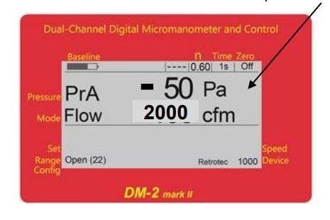
A calibrated fan is mounted on an outside door and blows air into or out of the dwelling. The fan creates a test pressure of 50 Pa (similar to a 30 km/h wind) which is displayed on channel A of the meter.
Channel B displays the fan pressure signal, which can be displayed as CFM or air changes per hour, depending on the selection made on the "Mode" key.
- A panel temporarily seals a door and provides a hole for mounting the fan.
- A calibrated door fan creates the test pressure and airflow.
- A meter shows the leakage from the house.

Air leakage tests for Blower Door.
Follow the steps on the Building Air Leakage Test Form at the bottom of the page.
- Step 1: Validate and record the required volume measurement.
- Confirm the preparation of the building according to steps 2 to 6.
- The equipment should be set up using the Quick Guide or use the blower door manual if additional guidance is needed.
- Note the range in step 7, which can be verified in the image.
- Note the device shown on the pressure gauge in step 8, which should match the installed fan.
- Verify that a test pressure of 50 Pa has been reached for step 9.
- Record the pressure in channel A and the CFM in channel B in step 10.
- Note the CFM @ 50 Pa that is activated from the "Mode" key on the pressure gauge.
The house can be pressurized, but a depressurization test (expelling the air from the building) is the most common. The advantage is that the exhaust and dryer dampers are closed during the test. Note the direction in step 11, as this may be necessary if the test is repeated.
Air changes can be read directly on the meter or the results can be calculated and entered in step 12.
Press [Mode] until "Air Chg @ 50 Pa" appears, press [Volume], enter the volume and the air changes will be displayed. (You can also multiply CFM x 60 to get CFH and divide by the volume to get the Air Changes).

Avoid major sources of error.
A wrong device or range setting could cause errors of 25 to 80%.
Make sure that the blower being used for the test is selected as "Device" on the meter. If the tester is using the Retrotec 1000 blower, "Retrotec 1000" should be displayed on the gauge.
Rings and range plates are used to provide more airflow for leaky houses, and less for better insulated houses.
Make sure the "Range Config" selection on the meter matches the Range Ring or Plate installed on the fan to avoid large errors. "Open" is for more leaky homes and "L" ranges are for tight homes (or very small buildings).
Damaged, clogged or pinched tubes and meter calibration could cause errors of 25 to 95%.
To check for clogged, leaking or pinched tubes, and to check if a gauge needs to be calibrated at the factory, simply connect each of the tubes between the different ports and compare the pressure readings shown in "PrA" and "PrB". If the values do not match within 2%, check the tubes for leaks, pinches, water or other obstructions. If the tubes are OK, it may be necessary to send the gauge to the factory for calibration before the results can be relied upon again.
- Press [Mode] until "PrB" appears in "Mode" (so the pressure gauge reads the pressure in both channels).
- Connect the yellow tube between the red and yellow ports of the meter.
- Check that the readings are within 2%.
- Repeat with each tube between other ports to check that the tubes are not leaking.
Repeat with a tube between gauges to check the calibration of the gauges.

These have been the most common errors, follow the table below to review the settings:

Building air leakage test form.
Fecha ____________________________________
Fan model__________________________________ Serial No. #__________________________
Digital Meter Serial No. #____________________________
Dirección_______________________________________________ Contacto_____________________________ Phone___________________________
Technician's name______________________________
Step | X | Task | Details and results |
1 |
| Measure the conditioned volume of the house here and at the meter.
|
__________ conditioned volume of m³. |
2 |
| Prepare the building as specified in the Blower Door Quick Guide.
|
|
3 |
| Close and seal all outlets to the outside, for continuous ventilation and HRV systems. |
|
4 |
| Close fireplace and stove doors, leaving the flue closed but not sealed. | Fireplaces should be cool and ashes covered or removed so as not to soil the house during the test. |
5 |
| Open all interior doors in the area to be tested and close all doors and windows to the outside. |
To achieve uniform pressure inside the enclosure. |
6 |
| Install the Blower Door on the open outer door and make connections according to the Quick Guide. |
|
7 |
| Record the "Range Config" range on the meter.
| __Open(22), __A, __B, __C8,__ C6, __C4,__ C2, __C1, __ L4, __L2, __L1 |
8 |
| Record "Device" on the meter. | __ Retrotec 1000, __ Retrotec 2000 __ Retrotec 3000, __ Retrotec 3000SR |
9 |
| Generate a pressure of 50 Pa in the house.
|
|
10 |
| Record the pressure "PrA" and the "Flow" of the pressure gauge. Record "Flow" with the indication "@ 50 Pa". | ___ Pa, ____ CFM (without running "@ 50 Pa") _____ "CFM @ 50 Pa" executed. |
11 |
| Record the direction of the current.
| ___ inserting air, ___ extracting air |
12 |
| Record air changes per hour.
|
_______ /h |
13 |
| Maximum air changes allowed: 7 /h
|
___ exceeded, ___ not exceeded |
14 |
| Turn heating and hot water equipment back on and remove the temporary sealing tape. |
Leave the house in the same condition in which you found it. |
Related Entries

AirTracer: Retrotec's new portable smoke generator
This portable smoke generator has been designed with convenience and accuracy in mind, providing an effective solution for leak location in a wide variety of applications, from construction to critical space ventilation systems.

SOLO, the new pressure gauge from Retrotec
With the aim of improving energy efficiency and accuracy in airtightness testing in buildings, we introduce Retrotec's Solo manometer, a compact and advanced tool designed to facilitate the pressure evaluation process in the building envelope.

Blower door systems in clean rooms
Blower Door systems offer a number of benefits for cleanrooms